 |
 |
|
5 PCI slots and 1 AGP Pro slot. Gigabit
Ethernet using Intel® 82540EM Gigabit Ethernet Controller
chipset. ITe I/O controller chip ITE I/O IT8712F-A. Realtek ALC650 CODEC for 6 ch audio.
|
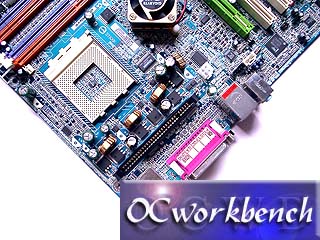
The Socket A, DPS slot, heatsink for the
north bridge. A 3 phase design is implemented. |
 |
 |
|
On the side of the board are connectors for 1394 ports, USB
brackets. The green coloured IDE ports are the IDE RAID supported by the
GigaRAID chipset. The two Red SATA ports are supported by the SiliconImage
Sil3112A chipset. |
4 DIMM slots supporting up to
3GB of
DDR266/DDR333/DDR400 using 184pin unbuffered DDR. On the Gigabyte board, they
split Channel 2 and Channel 4 into 2 DIMMs respectively.
DIMMs 1 + 3, DIMMs 2 + 4 are pairs. 3GB is possible with
2 x 1G + 2 x 512G. All supports double-sided RAM, but sometimes it might not
work perfectly depending on the individual brand and RAM quality, as RAM
are not standardized. The beauty of the design is that it offers more possible
RAM combinations. There is no major difference from conventional 3 DIMM
slot designs by other manufacturers. Please refer manual for specific
instructions to run in dual mode.
|
 |
 |
|
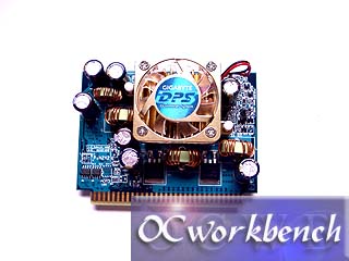
The DPS socket for plugging in
the DPS unit shown on the right hand side. |
DPS Unit |
 |
 |
|
Colour coded front panel as seen on previous Gigabyte
boards. It helps you to identify the pins correctly. 2 SATA ports
supported by Sil3112A chipset for RAID 0. GigaRAID chipset supports 2
channels of IDE RAID 0,1,1+0. South bridge of this board is a MCP-T.
|
SATA bracket for connecting to the on board SATA connectors
so that HDD can be connected outside the PC casing using SATA. |
 |
 |
|
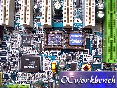
A close up view of the Dual BIOS, GigaRAID chipset and the
RTL 8801 chipset. |
According to Gigabyte, the C1 stepping (as detected by
WCPUID) is in fact the nForce2 Ultra 400. They also mentioned that in
future boards, the label will indicate nforce2 ultra 400 and they are the
same chipset. |